ST-0807RGB
RGB LED Chip Specifications
| Revision | Issued Date | Revised Item and Content | Note |
|---|---|---|---|
| 01 | 2023-07-20 | Original | |
ST-0807RGB
RGB LED Chip Specifications
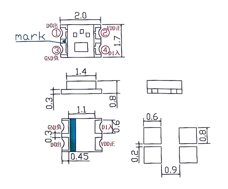
- Package size: 2.0×1.7×0.8mm
- Color: RGB
- Package: White transparent resin
- EIA standard packaging
- Environmental product, RoHS compliant
- For infrared reflow soldering process
Remark:
[1] All dimensions are millimeters (mm)
[2] Tolerance is ±0.1mm unless otherwise noted.
ST-0807RGB
RGB LED Chip Specifications
| Parameter | Symbol | Maximum Rating | Unit |
|---|---|---|---|
| Power Dissipation | Pd | Red: 70 | mW |
| Green: 85 | |||
| Blue: 80 | |||
| Peak Forward Current (1/10 duty, 0.1ms pulse) |
IFP | Red: 70 | mA |
| Green: 100 | |||
| Blue: 80 | |||
| Forward DC Current | IF | Red: 20 | mA |
| Green: 20 | |||
| Blue: 20 | |||
| Reverse Voltage | VR | Red: 5 | V |
| Green: 5 | |||
| Blue: 5 | |||
| Operating Temperature | Topr | -30°C ~ +85°C | °C |
| Storage Temperature | Tstg | -40°C ~ +90°C | °C |
| Soldering Conditions | Tsol | Reflow: 260°C, 10s Hand: 350°C, 3s |
°C |
| Parameter | Symbol | Color | Min. | Typ. | Max. | Unit | Test Condition |
|---|---|---|---|---|---|---|---|
| Forward Voltage | VF | Red | 1.7 | 1.9 | 2.2 | V | IF = 2.5mA |
| Green | 2.4 | 2.8 | 3.0 | ||||
| Blue | 2.4 | 2.8 | 3.0 | ||||
| Reverse Current | IR | Red | -- | -- | 10 | μA | VR = 5V |
| Green | -- | -- | 10 | ||||
| Blue | -- | -- | 10 | ||||
| Peak Wavelength | λP | Red | -- | 630 | -- | nm | IF = 2.5mA |
| Green | -- | 525 | -- | ||||
| Blue | -- | 462 | -- | ||||
| Dominant Wavelength | λd | Red | -- | 621 | -- | nm | IF = 2.5mA |
| Green | -- | 520 | -- | ||||
| Blue | -- | 468 | -- | ||||
| Spectral Bandwidth | Δλ | Red | -- | 20 | -- | nm | IF = 2.5mA |
| Green | -- | 35 | -- | ||||
| Blue | -- | 25 | -- | ||||
| Luminous Intensity | IV | Red | -- | 70 | -- | mcd | IF = 2.5mA |
| Green | -- | 240 | -- | ||||
| Blue | -- | 60 | -- | ||||
| Half Intensity Viewing Angle | 2θ1/2 | -- | -- | 120 | -- | deg | IF = 2.5mA |
ST-0807RGB
RGB LED Chip Specifications
Forward Current Vs. Forward Voltage
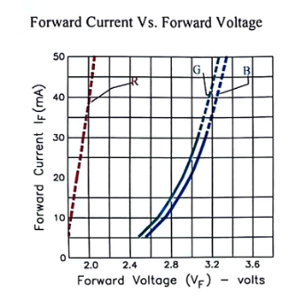
Shows I-V characteristics for Red, Green, and Blue LEDs
X-axis: Forward Voltage VF (V)
Y-axis: Forward Current IF(mA)
Temperature: Ta=25°C
Luminous Intensity Vs. Forward Current
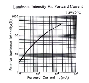
Relative luminous intensity vs current relationship
X-axis: Forward Current IF(mA)
Y-axis: Relative Luminous Intensity(%)
Temperature: Ta=25°C
Forward Current Derating Curve
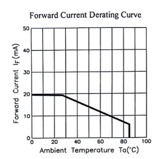
Current derating vs ambient temperature
X-axis: Ambient Temperature Ta(°C)
Y-axis: Forward Current IF(mA)
Shows thermal derating characteristics
Radiation Diagram
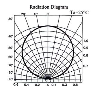
Polar radiation pattern diagram
Shows beam angle and intensity distribution
Temperature: Ta=25°C
Angular radiation characteristics
Spectrum Distribution
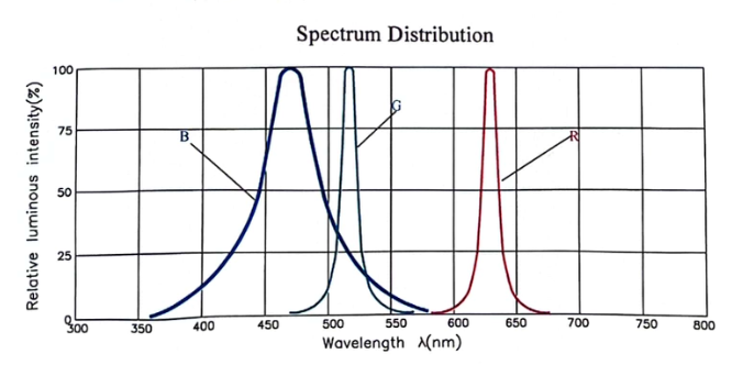
Wavelength spectrum for Red, Green, and Blue emissions
X-axis: Wavelength λ(nm)
Y-axis: Relative Luminous Intensity(%)
Shows spectral characteristics of each RGB color
Peak wavelengths: Red ~630nm, Green ~525nm, Blue ~462nm
Note: All characteristic curves are measured under standard test conditions (Ta=25°C) using Golden CZ standard test equipment. Actual performance may vary with operating conditions.
ST-0807RGB
RGB LED Chip Specifications
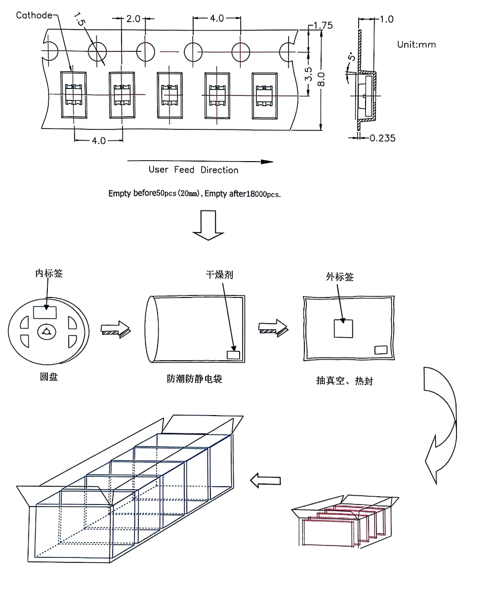
• Tape and reel specifications with dimensions
• Cathode orientation and feed direction
• Packaging flow: Inner label → Desiccant → Outer label
• Anti-static bag → Vacuum seal → Final packaging
• 3D packaging diagrams
Packaging Specifications:
- Tape Width: 8.0mm
- Pitch: 4.0mm
- Perforation: 1.5mm diameter
- Component Spacing: 2.0mm
- Side dimensions: 3.5mm height, 0.235mm thickness
- Empty before: 50pcs (20mm)
- Empty after: 18000pcs
- Unit: mm
Packaging Process:
- Reel with inner label identification
- Desiccant packet for moisture control
- Moisture-proof anti-static bag
- Vacuum sealing and heat sealing
- Outer label with product information
- Final carton packaging for shipping
Label Information includes:
- Company name: Golden CZ
- Model name: ST-0807RGB
- Manufacturing date
- Quantity
- Electro-optical parameters
- Batch/lot number
ST-0807RGB
RGB LED Chip Specifications
| Parameter | Symbol | Range | Unit |
|---|---|---|---|
| Logic Supply Voltage | VDD | 3.0 ~ 7.5 | V |
| R/G/B Output Port Voltage | VH | 9 | V |
| Logic Input Voltage | VI | -0.5 ~ 5.5 | V |
| Operating Temperature | Topr | -40 ~ +85 | °C |
| Storage Temperature | Tstg | -50 ~ +150 | °C |
| ESD Voltage | VESD | 5K | V |
ST-0807RGB
RGB LED Chip Specifications
| Parameter | Symbol | Min. | Typ. | Max. | Unit |
|---|---|---|---|---|---|
| Chip Input Voltage | VDD | 3 | 5 | 7.5 | V |
| R/G/B Output Port Voltage | VH | 8.5 | 9 | 9.5 | V |
| R/G/B Output Port Current | IO | 2 | 2.5 | 3 | mA |
| High Level Input Voltage | VIH | 0.7VDD | 0.9VDD | VDD | V |
| Low Level Input Voltage | VIL | 0 | 0.1VDD | 0.3VDD | V |
| DOUT High Level Drive Current | IOOH | - | 15 | - | mA |
| DOUT Low Level Drive Current | IOOL | - | 30 | - | mA |
| PWM Frequency | fPWM | 3 | 4 | 5 | kHZ |
| Supply Current | IDD | 0.15 | 0.3 | 0.45 | mA |
| Parameter | Symbol | Min. | Typ. | Max. | Unit | Test Condition |
|---|---|---|---|---|---|---|
| Data Transfer Rate | FDIN | - | 800 | 1100 | kHz | - |
| Transfer Delay Time | tPLZ | - | - | 200 | ns | DIN → DOUT |
| Output Current Turn-on Time | Tr | - | - | 400 | ns | VDD=1.5V IO=2.5mA |
| Tf | - | - | 400 | ns |
This chip adopts single-wire communication method and uses a return-to-zero coding format for data transmission. After the chip is powered on, the DIN port receives incoming data. After receiving 24 bits of data, the DOUT port starts to forward data to the next chip for cascading. During data transmission, if the DOUT port is directly connected, the chip will not receive new data. The chip has three PWM output ports: OUTR, OUTG, and OUTB, which respectively receive and drive the 24-bit data with different occupation ratios corresponding to different brightness levels. The signal frequency is 4kHz.
If the DIN port receives a RESET signal, the chip will display the received data. After receiving the signal, the chip will refresh and receive new data. After receiving 24 bits of data, it will be transmitted through the DOUT port. If the chip does not receive the RESET signal, the OUTR, OUTG, and OUTB outputs will remain unchanged.
After receiving more than 80μs of low level RESET signal, the chip will output the received 24-bit PWM data through OUTR, OUTG, and OUTB pins.
ST-0807RGB
RGB LED Chip Specifications
For example, if we design a 1024 level system, its refresh time would be 1024 × 0.4 × 2 = 0.8192ms (chip data delay time is 0.4μs), which does not affect the internal display effects.
| Name | Description | Typical Value | Tolerance |
|---|---|---|---|
| T0H | 0 Code, High Level Time | 0.295μs | ±0.05μs |
| T1H | 1 Code, High Level Time | 0.595μs | ±0.05μs |
| T0L | 0 Code, Low Level Time | 0.595μs | ±0.05μs |
| T1L | 1 Code, Low Level Time | 0.295μs | ±0.05μs |
| Trst | Reset Code, Low Level Time | ≥80μs | - |
Application Note:
The 0807 RGB uses a single polar return-to-zero code. Each code element must have a low level. This protocol's each code element starts with a high level, and the high level duration determines whether it is a "0" code or "1" code.
ST-0807RGB
RGB LED Chip Specifications
Note: D1 is data sent by MCU, D2, D3, D4 are data automatically reshaped and sent by each level circuit.
Note: High bit first, then RGB sequence data transmission
ST-0807RGB
RGB LED Chip Specifications
[1] Storage
A. After package sealing, storage conditions are Ta=5°C-30°C, RH<60%. Valid period on the package bag with qualified certificate is 30 days. If exceeding 30 days, baking is required. Baking conditions: 65°C ±5°C for 24 hours.
B. Before opening the package, first check if the package bag is leaking. If there is any leakage, please rebake before use.
C. After opening, please use under the following conditions: Temperature <30°C/RH<60% or below. The following baking treatment methods can be used:
a. Baking conditions: Product temperature in oven is 65°C ±5°C for 24 hours.
b. Remove product from package and rebake. Do not open oven door during baking process.
D. To avoid material moisture absorption leading to defects during customer production process, customers are requested to comply with the above requirements.
[2] ESD (Electrostatic Discharge Protection)
A. Static electricity and current surge can cause product characteristic changes, such as forward voltage drop, etc. In severe cases, it may cause product damage. Therefore, effective anti-static measures must be taken during use.
B. All related equipment and machines should be properly grounded, and other anti-static and electrical measures must be taken.
C. Use anti-static wrist straps, anti-static mats, anti-static work clothes, work shoes, gloves, and anti-static containers - all are effective anti-static and electrical measures.
⚠️ Important Notice:
Proper handling and storage procedures are essential for maintaining product quality and preventing damage. Please follow all guidelines carefully.
ST-0807RGB
RGB LED Chip Specifications
A. When designing circuits, the LED current should not exceed the specified maximum value. At the same time, protective circuits should be used. Otherwise, small voltage changes will cause large current changes, which may lead to product damage.
B. It is recommended to use circuit (A). This circuit can better regulate the current through each LED. Circuit (B) is not recommended. In this circuit, under voltage fluctuations, the LED forward voltage (VF) changes, and the current will change accordingly, which may cause the LED to be damaged by higher than specified current.
C. LED characteristics are easily affected by their own heating and environmental temperature changes. Temperature rise will reduce LED luminous efficiency, brightness attenuation, color shift, etc. Therefore, thermal management issues should be considered in design.
[3] Reverse Voltage Protection
Normal LED reverse current is very small and will not affect normal use. If the LED is subjected to excessive reverse voltage for a long time, the LED will be damaged. Reverse current will become too large, causing light emission failure. During design, attention should be paid to controlling reverse voltage. It is recommended not to exceed 10V for the LED reverse voltage.
[4] Temperature Protection
LED will heat up under high temperature conditions, increasing junction temperature and power. If used in high temperature environments for a long time, it is easy to cause failure. For high-density array applications, it is recommended that the ambient temperature during use should not exceed 55°C, and junction temperature should not exceed 75°C.
[5] Other Matters
A. Direct contact with the product surface by hand or contamination of the packaging surface may cause product performance changes due to static electricity and other factors. Direct contact may affect the internal lead frame and gold wire, so please handle the product with care. Especially when the product is in a high temperature state, do not use hard, sharp objects or apply excessive force to contact the packaging surface. Pay attention when using magnetic clasps for collection.
B. Please do not use self-driven LED products below standard current to ensure stable product characteristics.
C. When LEDs are used outdoors, please provide waterproof, moisture-proof and salt-proof protection.
🏁 End of ST-0807RGB RGB LED Chip Specifications
Golden CZ - Professional LED Solutions